Arduino Transistor Identification and Transfer Curve Tester - Part 1
At prokopyshen.com, we have a lot of transistors collected over the years. Many are unmarked and we are not always sure if the device is functional or has sufficient gain for our projects. Our solution was to build an Arduino based test device that wil positively identify each lead, the type (PNP vs NPN), material (Silicon or Germanium), and then collect enough data points for us to determine the gain and DC transfer characteristics.
To do this, we had to add some chips to extend the functionality of the Arduino. And to better integrate with our linux workstation, we used an Ethernet shield. Here is the block diagram:
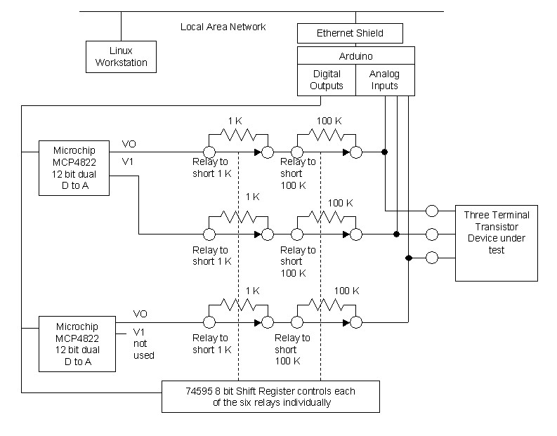
Microchip makes a precise and simple to program 12 bit Digital to Analog chip with dual output - the MCP4822 . I really like this chip because it has a range doubler, meaning you can program the output voltage in steps of either 1 mV ( max out of 2.047 V) or by 2 mV (max out of 4.094 V). We need three outputs - one for each terminal we will be testing, so while two chips are needed, the second output from the second chip wont be used. Arduino can easily handle all the programming of the MCP4822 DtoA chip for us.
The Arduino has a limited number of onboard digital outputs, and when you get serious about using this device you realize that they are very valuable. Fortunately, it is easy to extend the number of digital outputs using a 74595 8 bit shift register and it is also easy to program with the Arduino. The shift register will be used to on-demand short a series resistor from the DtoA chip to our transistor device under test. I used six old 5V reed relays I had around for this. Each DtoA output can be applied directly to the test terminal, or with either a 1K or 100K series resistor. Via the shift register, the Arduino can individually set each of the six relays as needed to select either resistor or direct (short) application.
The final piece is that each of the test terminals can now be fed to the Arduino analog input ports. These have reaonably high impedance inputs so I have found that a buffer is not needed.
At a high level, we can now set each transistor test port to any voltage between 0 and 4.096 V directly, and optionally with either a 1K or 100K resistor in series. The idea here is to pick a terminal and assume it is the emitter and set the voltage to 0 to act as current sink. Pick another terminal and assume it is the base, and apply a couple of volts to it thru a 100K resistor. The last terminal is assumed to be the collector, and we set it to 4.094 V with the 1 K resistor. The using the Arduino analog input attached to each test port, we see what voltages are actually appearing on our assumed base and collector. If the base voltage is around 0.6V (Silicon) or 0.2 V (Germanium), and we can see a few volts on the what we assume is the collector, then we have then successfully identifed the leads and can proceed to curve tracing. By applying a range of base currents and measuring collector currents occur, we can first convince ourselves that the device is behaving as a transistor and then work out the DC gain of the device.
There are only 12 possible combinations of base/collector/emitter for NPN/PNP devices, so testing all them and evaluating what we the device is behaving like doesnt take long.
In the next article, we will dig in to the actual wiring diagram and look at why I used relays. Your feedback and comments are always welcome - please ContactMe !