Arduino Transistor Identification and Transfer Curve Tester - Part 2
In part 1 of this series, we reviewed the block diagram and discussed the additional chips that I used for my Arduino based transistor identification and automated test tool. In this article, we will look at the wiring diagram. There is no critical wiring or timing path, so any of the common prototype or point-to-point wiring boards will do.
Drawing Page 1 shows the connections between Arduino, the two DtoA and the 8 bit shift register.
While I used an Arduino Duemilanove , adjustments could be made to fit any of the current models. Both the DtoA and the 74595 Shift Register require a single +5 VDC power supply. To be protective of the Arduino, and to ensure that the DtoA MCP4822 has the best possible stability, I built a +5V power supply for all external to the Arduino parts.
The Microchip MCP4822 is programmed via the SPI interface that is built in to the Arduino. We are only going to send data to the chip, so we need only Arduino pin 13 SPI SCK (the clock line) and pin 11 SPI MOSI (Master Out Slave In - the Master line for sending data to the peripherals). We used a dual DtoA so we used the general purpose pins 7 and 9 for chip selects. Both DtoA can share the same LDAC pin 5 (Latch, or transfer the input register to the output register to set the output voltage) which we assign to Arduino pin 8. So with just five wires, we have a total of four programmable DtoA outputs. The transistors we will be testing only have 3 leads, so only 3 of the outputs are sent to the relay board.
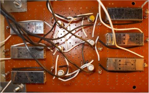
Drawing Page 2 is the schematic for the relay board.
While others have built and shared libraries for using shift registers, I rolled my own. The 74595 has a 8 bit serial in interface and a separate 8 bit parallel out shift register. This allows the input to be completely clocked in before it is transferred to the output. Only four connections from the Arduino are required to drive the shift register : SRCLK, nCLR, RCLK and SER.
We have six relays to drive, so shift register output QG and QH are no connection. And the best part is that we still have one digital i/o pin left spare on the Arduino for future use!
The transistors we will be testing have three leads which are inserted in test pins 0, 1 and 2. There are two relays per transistor lead. Via the shift register, the relay will short ( or place in series) a 1K or a 100K ohm resistor. The relays are driven by 2N2222 transistors with a 15K ohm base resistor and the coil has a protective diode.
I had some 5 VDC SPDT relays on hand so that is what I used. Any small relay ( small so that the contact settling time is low) you can get your hands on will work. Relays are used because we have to perform the resistor switching in series, and by using two of them, we can four combinations : a short circuit, 1 K, 100K and 101K. The last combo isn't of much use, but the first three will be.
In our next article we will take a look at the Arduino code to drive this. Your feedback and comments are always welcome - please ContactMe !